
🔄 Chilled Water Decoupler Loop
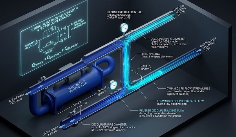
Size primary-secondary hydraulic decoupler bridge pipes, identify flow direction, mixed supply header degradation, and Low Delta-T syndrome penalties.
⚡ Fortran 90 Engine
Double Precision (IEEE 754)
✓ ISO / ASME Validated
 Hvac
Hvac
📊 Solver Telemetry
● ACTIVE
🔄 Primary-Secondary Chilled Water Hydronic Decoupler Bridge
Real-time visual simulation of production vs distribution flow balance, bridge direction & mixed temperatures📝 Configuration & Presets
✅ Forward Flow (200 / 175 m³/h)
⚠️ Reverse Deficit (150 / 220 m³/h)
📉 Low ΔT Syndrome (8.5°C Ret)
🏥 Hospital Plant (320 m³/h)
Decoupled Hydronic Formulations:
• Decoupler Flow: Qbridge = Qprim − Qsec
• Minimum Bridge Diameter: Dmin = √[ (4 · Qmax) / (π · vmax) ]
• Mixed Supply (Reverse): Tmix,sup = (Qprim Tsup + |Qb| Tret) / Qsec
• Low ΔT Penalty: Loss = [1 − (ΔTact / ΔTdes)] × 100%
• Decoupler Flow: Qbridge = Qprim − Qsec
• Minimum Bridge Diameter: Dmin = √[ (4 · Qmax) / (π · vmax) ]
• Mixed Supply (Reverse): Tmix,sup = (Qprim Tsup + |Qb| Tret) / Qsec
• Low ΔT Penalty: Loss = [1 − (ΔTact / ΔTdes)] × 100%
📊 Decoupler Sizing Results
📊 Output Summary
Recommended Decoupler Bridge Pipe Size
DN250 (Ø 250 mm)
🚨 REVERSE FLOW (Warning: Warm Return Degrades Coil Supply!)
-70.0 m³/h
Mixed Supply to Coils (Tmix,sup)
7.75 °C
Chiller Setpoint = 6.0 °C
Mixed Return to Chillers (Tmix,ret)
11.50 °C
Actual Secondary = 11.5 °C
Low ΔT Capacity Penalty
0.0 %
ΔTact = 5.5 °C (Des: 6.0 °C)
Decoupler Flow Velocity
0.40 m/s
Limit: ≤ 0.50 m/s
📈 Required Decoupler Diameter vs Bypass Flow
📉 Mixed Supply Temperature Degradation vs Secondary Overpumping
=================================================================
 THERMOFLUIDCALC — CHILLED WATER DECOUPLER ANALYSIS REPORT
=================================================================
Case Title                 : Severe Secondary Overpumping (Reverse Flow & Supply Degradation)
Primary Production Flow    : 150.00 m3/h (660.4 GPM)
Secondary Distribution Flow: 220.00 m3/h (968.7 GPM)
Decoupler Bypass Flow      : -70.00 m3/h
Hydronic Bridge Status     : 🚨 REVERSE FLOW (Warning: Warm Return Degrades Coil Supply!)
-----------------------------------------------------------------
MINIMUM DECOUPLER PIPE DIA : DN250 (250.0 mm ID)
Mixed Header Supply Temp   : 7.75 °C (Chiller out: 6.00 °C)
Mixed Header Return Temp   : 11.50 °C (Secondary out: 11.50 °C)
Low Delta-T Penalty        : 0.0 % capacity derating
=================================================================
📘 Calculation Methodology & ASHRAE Standards
Hydraulic Decoupling Bridge
The bridge pipe provides a zero pressure drop junction ($v \le 0.5\,\text{m/s}$), hydraulically isolating the constant-flow chiller loop from variable-flow loads:
Qbridge = Qprimary − Qsecondary
Reverse Flow & Low Delta-T Risks
If $Q_{secondary} > Q_{primary}$, warm return water flows backward across the bridge into the coil supply header, causing loss of space dehumidification control.
Key Engineering Assumptions
- Water velocity in decoupler bridge limited to $0.5\,\text{m/s}$ ($\Delta P < 1.5\,\text{kPa}$).
- Perfect adiabatic mixing at header tee junctions.
- Sized for max flow mismatch or 100% capacity of largest chiller module.