
🌊 Gradually Varied Open Channel Flow (Standard Step)
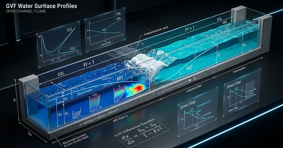
Model gradually varied open channel flow profiles (M1, M2, M3, S1, S2, S3 backwater curves): critical depth (yc), normal depth (yn), Froude number, and reach distance by Standard Step Method.
⚡ Fortran 90 Engine
Double Precision (IEEE 754)
✓ ISO / ASME Validated
 Fluid Mechanics
📊 Solver Telemetry
● ACTIVE
💡
Hardware & Sizing Partner: Need to size a control valve or check ASME flange bolt torque for this line?
🌊 Open Channel Longitudinal Profile & Water Surface Curve
Real-time visual simulation: Bed slope $S_0$, normal depth $y_n$, critical depth $y_c$, and backwater surface $y(x)$📝 Configuration & Presets
Gradually Varied Flow Dynamic Equation:
• Governing ODE: dy / dx = (S₀ − Sf) / (1 − Fr²)
• Friction Slope: Sf = n² · V² / Rh4/3
• Specific Energy: E = y + V² / (2 g) [meters]
• Standard Step Reach Distance: Δx = (E₂ − E₁) / (S₀ − S̄f).
• Governing ODE: dy / dx = (S₀ − Sf) / (1 − Fr²)
• Friction Slope: Sf = n² · V² / Rh4/3
• Specific Energy: E = y + V² / (2 g) [meters]
• Standard Step Reach Distance: Δx = (E₂ − E₁) / (S₀ − S̄f).
📊 Hydraulics Results
📊 Output Summary
Water Surface Profile Classification
M1 (BACKWATER)
Normal Depth yn: 2.54 m | Critical Depth yc: 1.25 m
MILD (M-Slope)
Normal Depth (yn)
2.54 m
Uniform equilibrium flow
Critical Depth (yc)
1.25 m
Fr = 1.0 threshold
Boundary Froude Number (Fr₀)
0.15
Subcritical Flow
Control Section Velocity
0.97 m/s
At y = 4.5 m
📈 Water Surface Elevation y(x) (m) vs Reach Distance x (m)
📉 Specific Energy Diagram E(y) (m) vs Water Depth y (m)
=================================================================
 THERMOFLUIDCALC — GRADUALLY VARIED FLOW (GVF) REPORT
=================================================================
Case Title                 : River Dam Impoundment (M1 Backwater Curve)
Channel Dimensions         : Bottom Width b = 8.00 m, Side Slope z = 0.00, Slope S0 = 0.00080, n = 0.022
Discharge & Control Depth  : Q = 35.00 m3/s, Boundary Depth y0 = 4.50 m
-----------------------------------------------------------------
NORMAL DEPTH (yn)          : 2.538 meters (Uniform Flow Level)
CRITICAL DEPTH (yc)        : 1.250 meters (Fr = 1.0 Minimum Energy)
SLOPE CLASSIFICATION       : MILD (M-Slope)
WATER SURFACE PROFILE      : M1 (BACKWATER)
Boundary Flow Velocity     : 0.972 m/s
Boundary Froude Number     : 0.146 (Subcritical)
=================================================================
📘 Calculation Methodology & Open Channel Hydraulics
Backwater Curve Classification
Profiles are categorized by slope (Mild $M$, Steep $S$, Critical $C$) and zone ($1: y > y_n > y_c$, $2: y_n > y > y_c$, $3: y_c > y$).
Standard Step Integration Method
Solves specific energy balance across reach increments $\Delta x$, accounting for boundary friction dissipation and non-uniform velocity distribution.
Key Engineering Assumptions
- Manning equation for reach-averaged friction slope $\bar{S}_f$.
- Prismatic channel geometry with steady one-dimensional flow.
- Applicable to river dam impoundments, canal drops, spillway chutes, and drainage systems.