
🔥 Gas Turbine Combustor (Lefebvre Model)
Size gas turbine combustor chambers: Lefebvre combustion volume and loading parameter, fuel flow, primary flame temperature, pattern factor OTDF, and liner geometry.
⚡ Fortran 90 Engine
Double Precision (IEEE 754)
✓ ISO / ASME Validated
 Turbomachinery
📊 Solver Telemetry
● ACTIVE
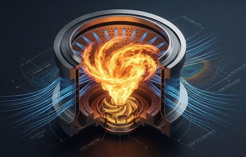
🔥 Combustor Liner, Swirler Flame & Dilution Jets
Real-time visual simulation: Fuel swirler primary flame, secondary mixing, and dilution air jets📝 Configuration & Presets
Lefebvre Combustor Formulation:
• Fuel Flow: ṁf = ṁa · [cpg·T4 − cpa·T3] / [ηc·LHV − cpg·T4] [kg/s]
• Lefebvre Loading: θ = [P31.75 · Vcomb · exp(T3/300)] / ṁa
• Thermal Duty: Q̇th = ṁf · LHV [MWth]
• Pattern Factor (OTDF): (Tmax − T4) / (T4 − T3) < 0.25.
• Fuel Flow: ṁf = ṁa · [cpg·T4 − cpa·T3] / [ηc·LHV − cpg·T4] [kg/s]
• Lefebvre Loading: θ = [P31.75 · Vcomb · exp(T3/300)] / ṁa
• Thermal Duty: Q̇th = ṁf · LHV [MWth]
• Pattern Factor (OTDF): (Tmax − T4) / (T4 − T3) < 0.25.
📊 Performance Results
Configure inputs and click Compute to view results.
📘 Calculation Methodology & Combustor Standards
Lefebvre 3-Zone Combustor Architecture
Combustion air is metered into a primary reaction zone (25–30%) for flame stabilization, intermediate zone (20–25%) for CO burnout, and dilution zone (45–55%) to shape the radial temperature profile for the downstream turbine.
Pattern Factor & Liner Sizing
Overall Temperature Distribution Factor (OTDF) measures peak circumferential temperature hotspots, preventing turbine nozzle guide vane melting.
Key Engineering Assumptions
- Lefebvre semi-empirical combustion loading formulation.
- Annular and can-annular configurations.
- Widely used in aero-engines, power generation gas turbines, and hydrogen combustors.